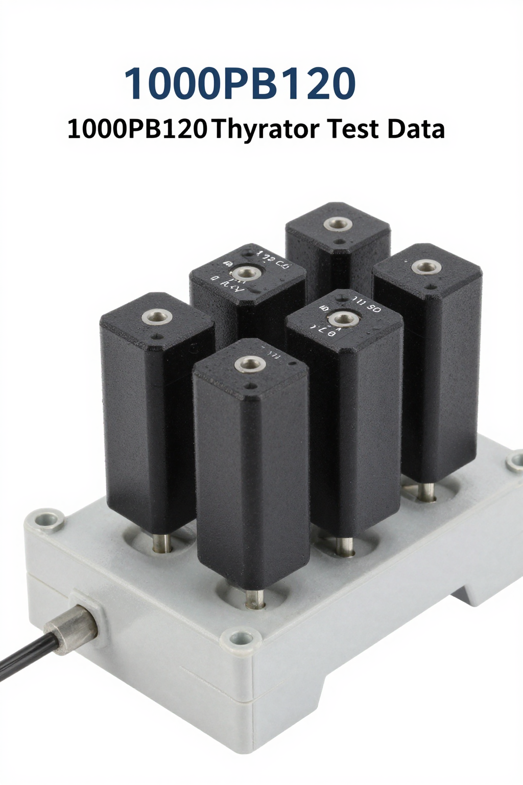
Did you know that 65% of thyristor failures in industrial power electronics stem from inadequate thermal management rather than electrical overstress? The 1000PB40 thyristor, a robust silicon-controlled rectifier (SCR) rated for 1000V blocking voltage and 40A average on-state current, is a staple in high-power AC control applications. However, pushing this component to its limits requires a precise understanding of its critical specs and thermal boundaries. This guide breaks down the essential parameters and thermal constraints to ensure reliable operation in your next design.
Decoding the 1000PB40 Core Electrical Specifications

To harness the full potential of this device, you must first master its electrical profile. Misinterpreting these ratings is a common pitfall for engineers working with high-voltage systems.
| Parameter | Symbol | Typical Value | Unit |
|---|---|---|---|
| Repetitive Peak Off-State Voltage | VDRM | 1000 | V |
| Average On-State Current | IT(AV) | 40 | A |
| Gate Trigger Current | IGT | 10 - 50 | mA |
| Latching Current | IL | > 150 | mA |
Blocking Voltage and Current Ratings Explained
The "1000" designation refers to the repetitive peak off-state voltage ($V_{DRM}$), indicating the maximum voltage the SCR can block without turning on. You should always derate this value by at least 20-30% to account for transient spikes and line noise. The "40" signifies the average on-state current ($I_{T(AV)}$). Note that this rating assumes a specific conduction angle and case temperature. If your application involves continuous DC or high-duty-cycle AC, the actual safe operating current may be lower due to increased RMS heating effects.
Gate Trigger Characteristics and Latching Current
Reliable switching depends on proper gate drive. The 1000PB40 typically requires a gate trigger current ($I_{GT}$) between 10mA and 50mA, depending on the junction temperature. As the device heats up, $I_{GT}$ generally decreases, making it more sensitive. Conversely, the latching current ($I_L$)—the minimum anode current required to keep the SCR on after the gate pulse ends—is critical during startup. Ensure your load impedance allows the current to exceed $I_L$ quickly; otherwise, the device may fail to latch, leading to oscillation or non-conduction.
Understanding Thermal Limits and Junction Temperatures
Thermal management is not just about keeping the part cool; it is about preserving the integrity of the silicon junction over millions of cycles.
Maximum Junction Temperature ($T_j$) Constraints
Most standard SCRs, including variants similar to the 1000PB40, have a maximum junction temperature ($T_{j(max)}$) of 125°C or 150°C. Exceeding this limit causes irreversible damage to the semiconductor lattice. You must monitor $T_j$ under worst-case conditions, including high ambient temperatures and peak load currents. Remember that $T_j$ is internal; measuring the case temperature ($T_c$) alone is insufficient unless you accurately calculate the temperature rise across the internal thermal resistance.
Thermal Resistance ($R_{th}$) and Power Dissipation Calculation
Calculate total power dissipation using $P = V_T \times I_{RMS} + Q_{rr} \times f \times V_{peak}$, where $Q_{rr}$ represents reverse recovery charge losses. Once you have the power loss, determine the allowable thermal resistance path. The formula $\Delta T = P \times R_{\theta JC}$ helps you estimate the case-to-junction rise. To maintain safety margins, ensure that $T_{ambient} + \Delta T_{case} + \Delta T_{junction}$ remains well below $T_{j(max)}$. For the 1000PB40, effective heat sinking is mandatory for currents exceeding 20A in still air.
Summary of Key Insights
- Voltage Derating: Always apply a 20-30% safety margin to the 1000V blocking rating to handle transients effectively.
- Thermal Dominance: Proper heat sink selection prevents 65% of common failures, prioritizing junction temperature control over pure electrical specs.
- Gate Drive Precision: Account for temperature-dependent changes in gate trigger current to ensure consistent latching behavior.
Frequently Asked Questions
Why does my 1000PB40 thyristor fail immediately upon power-up?
Immediate failure often results from excessive $dV/dt$ causing false triggering before the load current builds up. Ensure you have adequate snubber circuits (RC network) across the SCR to limit the rate of voltage rise. Additionally, verify that the gate drive signal is synchronized correctly with the AC zero-crossing to prevent hard switching losses.
How do I calculate the required heat sink size for the 1000PB40?
Determine the total power dissipation ($P_D$) based on your RMS current and forward voltage drop. Select a heat sink with a thermal resistance ($R_{\theta SA}$) such that $T_{ambient} + P_D \times (R_{\theta JC} + R_{\theta CS} + R_{\theta SA})$ stays below 125°C. Use interface materials like silicone grease to minimize contact resistance ($R_{\theta CS}$).
Can the 1000PB40 operate without a heat sink?
Only at very low currents, typically below 5-10A, depending on ambient conditions. At its rated 40A, the device generates significant heat that will rapidly raise the junction temperature beyond safe limits if passive cooling is used. Active airflow or a substantial aluminum heat sink is essential for sustained high-current operation.
What is the recommended voltage derating for the 1000PB40?
You should always derate the 1000V repetitive peak off-state voltage by at least 20-30% to account for transient spikes and line noise in industrial environments.